


Getting a model ingame
|
|
|
|

This tutorial is to show you how to get from a finished model in Max to a model ingame.
You should be starting with a completed model with a shader applied as per my previous tutorial.
To make things easier I'll only be focusing on getting the model (my Tiger I Tank) out of Max correctly and into the game as a new image for the GDI Predator Tank. I will do a later tutorial on inserting an entire new unit into the game, which will start where this tutorial leaves off.
There is a more complicated way of setting up your model involving the WWSkin space warp and tying model parts to bones, this helps with optimisation as you can have your model as one mesh (the SDK mentions that one "chunk" is better than several). I won't be covering it in this tutorial though.
The first thing to do is make sure your model is set up correctly for the game in Max.
For a basic tank (and the vast majority of other units) you're interested in a few key things, these are:
Texture names - this has an affect on your directory structure later.
The "bounding box" - this box is for the game to process collision detection.
Muzzle flash - this sits on the end of your barrel and appears when the unit fires ingame, it has the shader for muzzle flash effects applied to it.
Treads - the treads in C&C3 move, but the game actually shows a different mesh depending on whether the unit is moving or not.
Other bits - for basic tanks you'll be wanting bones for the treadprint effect to appear from, you may also have some upgrade parts.
Pivots - changing these lets the game know what points the model's parts should rotate around.
Linking - linking makes a mesh move with the mesh it is linked to, for example linking your barrel to a turret means that the barrel will follow the turret when the turret rotates.
So let's get started.
The names of your textures directly affects the folder they need to be in under "YOURSDKDIRECTORY/Art/". The mod builder and W3X viewer both look through a model file for texture names, they then look for those textures in a folder named with the first two letters of the texture name. For example, GUTigerTank.tga would need to be in "YOURSDKDIRECTORY/Art/GU/". It's a good idea to have all your textures using the same first two letters in their filename as that means they all go in the same directory.
EA does this by using a naming convention for textures (and models), "[FACTION][OBJECTTYPE][NAME][EXTRA]" is the most common occurrence.
A file using this convention would be GUTigerTank_NRM.tga. G stands for GDI, the faction. U stands for Unit, the object's type. TigerTank is the name used for that object. _NRM is the suffix to tell you a file is a normal texture map (other examples of this - _SPM for specular map, _FP for a formation preview model).
You can make up your own convention if you don't like EA's.
Pick box next.
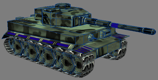
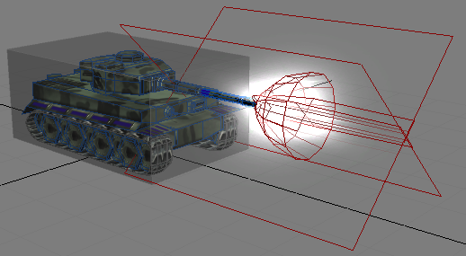
This is our model, with the correct shader applied (ObjectGDI.fx in this case).
Using the standard create tools make a "Box", set the length/width/height segs to 1 if it hasn't defaulted to that already. Now right click on the box, go to "Covert To" and then "Convert to editable mesh". To make life easier right click the box again and go to "Properties", on the left tick the box for "See-through" - the box now goes semi-transparent. Go to the "Modify" tab now and modify your box to fit your model.
The result should be something like this:
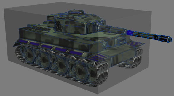
Don't worry about the barrel, EA have left all of theirs sticking out of the box and the barrel's position changes drastically depending on where your turret is pointing. Don't apply any material to this box.
Name the box something sensible, EA call them "OBBox". You can save yourself some coding by keeping their naming conventions.
Now that our unit isn't going to overlap with other units you can think about muzzle flash.
EA's muzzle flash mesh looks like this:
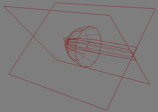
It's also UV mapped to use the correct parts of fxmuzzle.tga.
Rather than trying to recreate this yourself you can merge it from one of the sample art files (you can bypass alot of the setup procedure by bringing in all the rigging from one of the sample models) or you can merge the one from the link below (taken from the GDI Predator) which includes the .tga texture and .xml file for it. The mesh should be called "FXMuzzleFlash"
Muzzle Flash - .max file for mesh, .tga and .xml for texture, 147kb - Download
Position the mesh so the beginning of the centre mesh is on the end of your barrel like so:

You may notice this mesh has keyframes on the slider at the bottom of the screen, this is a material animation so you don't need to export the model as an animation later.
If you want to see the texture in the Max viewports you need to select the muzzle flash mesh, bring up the material editor, click "Get Material" and choose "Browse from:" "Selected". Now drag the material into an empty slot in the material editor.
The muzzle flash shader gives you these options:
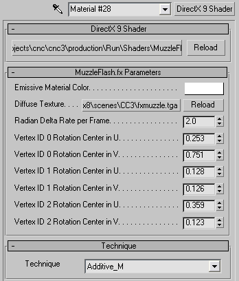
The top filepath points to the wrong shader location but the shader still gives the correct options. For tidyness' sake you can click the top filepath button and browse to where your MuzzleFlash.fx is located (YOURMAXDIRECTORY/maps/fx/CnC3/MuzzleFlash.fx by default) but it doesn't actually make any difference.
You are however interested in the "Diffuse Texture" filepath button, as this points to the wrong texture location which does make a difference. Click the button and browse to the correct location for "fxmuzzle.tga" on your PC.
Once this is corrected your viewport view looks like this:
Now you've got a nice muzzle flash effect, treads are up next.
These are a little awkward. Them working basically hinges on you having a texture of the treads in which the tread runs horizontally (the .xml files note that treads will only animate through U and not V) and is shown running both ways.
That's a horrible explaination, so EA's files to the rescue again, here's the Predator's tread texture.
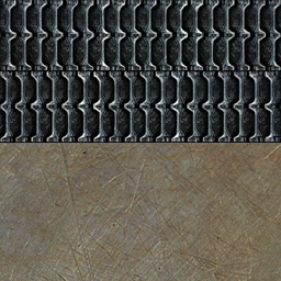
As you can see, the treads go horizontally. The top version is facing left and the bottom version is facing right.
For this part of the tutorial I'm switching to the Predator's treads because my Tiger's are pretty ugly.
The shaders for the treads have complex settings (one of the shaders is animated too) and it's a waste of time to go through everything here when you can use EA's shaders.
Treads - .max file for mesh, .tga and .xml for textures, 320kb - Download
This file contains a .max file of the Predator treads. Open your material editor and go to "Get Material", select "Browse From" "Mtl Library" and click open. Browse to the location of the .max file in the zip above, change the "Files of type" dropdown to "3ds max (*.max)" and open the "GUPredTankTreads.max" file. Two shaders appear, "Stop" and "Move" - drag both of these into empty slots in the material editor. As with the muzzle flash the shader is pointing to incorrect file locations, so correct them with the file locations on your system. You need to change "Base Texture" and "Secondary Texture" to show the location of GUPredatorTreads.tga (included in the .zip above) or your own treads texture. You must do this for both shaders.
Now the shaders are ready you need to prepare the meshes. You need four copies of your treads mesh (your treads mesh should be both your left and right treads in one mesh, or all four in the case of the Predator) so clone your mesh three times (the "Select and Move" tool combined with holding shift while clicking is a quick way to do this).
Name these meshes "TreadsLeft" (mesh to be shown when turning left), "TreadsRight" (mesh to be shown when turning right), "TreadsStop" (mesh to be shown when still) and "TreadsMove" (mesh to be shown when moving).
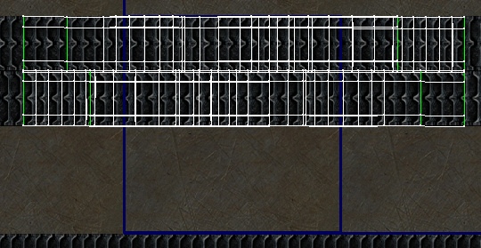
The meshes need to be UVW unwrapped like so:
"TreadsStop" - Treads from both sides mapped to the top line.
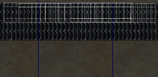
"TreadsMove" - Treads from both sides mapped to the bottom line.
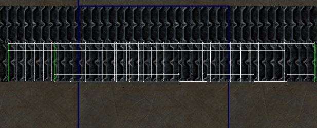
"TreadsRight" - Left set of treads mapped to the bottom line, right set of treads mapped to the top line.
"TreadsLeft" - Right set of treads mapped to the bottom line, left set of treads mapped to the top line.
Now apply the "Move" shader to "TreadsMove", "TreadsRight" and "TreadsLeft" meshes. Apply the "Stop" shader to the "TreadsStop" mesh.
To test this, click in a smooth and highlights viewport and:
Hide all geometry except "TreadsMove", then move the animation frame slider - you should find that both sets of treads move in the same direction.
Hide all geometry except "TreadsRight", then move the animation frame slider - you should find that the right set of treads moves backwards, while the left set of treads moves forwards.
Hide all geometry except "TreadsLeft", then move the animation frame slider - you should find that the right set of treads moves forwards, while the left set of treads moves backwards.
Your treads are now complete.
Next up is a quite short section on "other bits".
It's sensible to make sure your turret is called "turret" and your barrel is called "barrel". This saves you having to change code to refer to your own mesh names.
In a really standard tank the only other bones you really need to worry about are the bones to define where the tread print effect is drawn from (the "footprints" of the tank ingame). For these you want two small boxes with all the segs set to 1 (like with the bounding box), you should position them under the tank's treads like this (the bones are the pink objects):
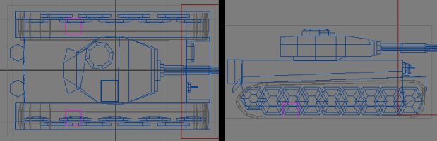
These need to be named something you can remember. Again you can save yourself some coding by using EA's names which are FXTracksL for the bone under the left tread and FXTracksR for the bone under the right tread (for the Predator Tank at least).
If your unit is designed to take an upgrade it's nice to have some extra geometry appear when it does (think GDI's railgun upgrade and the new barrels that appear on your tanks). To acheive this you just need to have a seperate mesh for your additional part(s). Staying with the railgun example, the Predator has an extra mesh for the second the barrel called "UGRail01" positioned as it should be when it appears ingame. This mesh is defined in the code as appearing when triggered by the railgun upgrade.
Now onto pivots.
You may or may not have to change pivots depending on where they are already in your meshes. Basically you need the mesh's pivot set at the point it will rotate from.
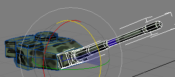
To show what I mean I've hidden everything except my barrel and turret meshes.
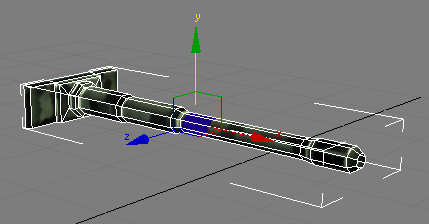
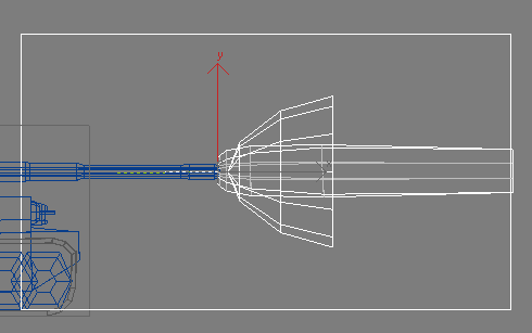
This tends to be the default place for a pivot, in the centre of the mesh. If you rotate the mesh with the pivot set here...
This happens. As you can see my barrel is now levitating in mid air and is no conctact with the turret whatsoever, you need to move the pivot to a place that the barrel can rotate realistically relative to the turret.
To do this you head to the "Hierachy" tab on the right of the screen (the next one along from "Modify", two along from "Create" if you've never encountered it before). Then select "Affect Pivot Only".
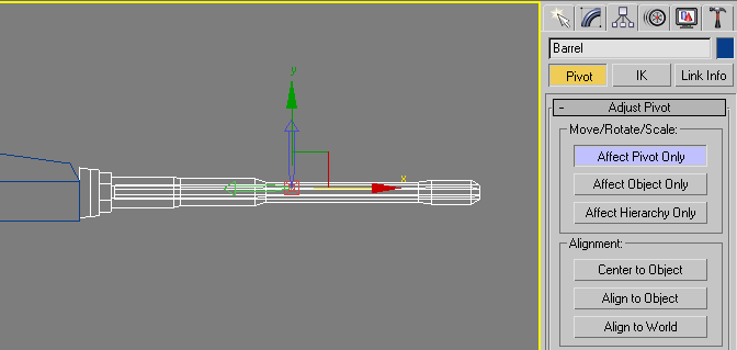
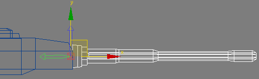
The pivot of your mesh will now respond to the normal "Select and..." tools for rotating and moving. Select the move tool and move your pivot to a more realistic location, in the case of my barrel it wants to be near the turret end of the barrel mesh. The pivot doesn't have to be "inside" the mesh either, you can have it anywhere in your scene.
Click the "Affect Pivot Only" button again to revert to controlling meshes rather than pivots.
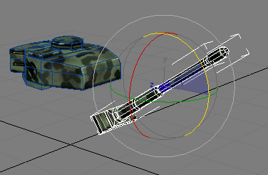
Now when my barrel mesh rotates it rotates around its new pivot like this:
Though I'm not planning on implementing barrel movement for this model the same rules apply to any mesh that the game is going to rotate (you may want to adjust your turret pivot so it rotates around a point that looks good for example).
All your parts are done now, you just need to link them up so they behave correctly ingame.
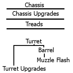
If you exported the model now and got it ingame you'd find that the chassis, turret and treads would behave as they should but the barrel will follow the chassis rotation instead of the turret.
This is because the game reads the meshes based on whether you've told it what they are:
The mesh defined as the turret in your code is the turret - this rotates to aim and fire.
The meshes defined as the bones discussed above are hidden from view - except the treads and muzzle flash meshes, which are shown when needed.
Anything else is considered part of the chassis - so it will move with the chassis unless the game knows otherwise.

This button will help you fix that, it's the "Select and Link" button - by default it is convieniantly located in the top left corner of Max next to the Redo button.
To use it - click on it, click the mesh you want to be the subordinate (I start with the muzzle flash mesh) then click again and drag to the mesh you want to link to (the muzzle flash would be linked to the barrel). A dotted line is drawn as you drag and when you release the mouse the second mesh you select will flash so you can tell if you got the right mesh.
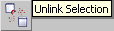
If you miss the mesh and find that a different mesh flashes you can easily break a link using the "Unlink Selection" button, which is next to the "Select and Link" button. Simply select the mesh you want to unlink and click the "Unlink Selection" button, this will break all links affecting that mesh.
Once you've linked the muzzle flash to the barrel, you need to link the barrel to the turret. You also need to link any loose meshes that should rotate with your turret to it (like upgrade meshes).
When you're done select your turret mesh (and only your turret mesh) then move or rotate it using the "Select and..." buttons, you should notice that the barrel and muzzle flash meshes (and any other parts linked to the turret) move with the turret. If you move/rotate your barrel you should find that the muzzle flash mesh moves with it but the turret stays still.
You don't need to link your turret to the chassis so that's the model all linked up.
You're just about done in Max now, only exporting left.
Head to "File" then "Export". A file browser window pops up so browse to "YOURSDKDIRECTORY/Art/".
Now consider the naming convention I mentioned earlier in my case I have a GDI unit so I need to create a folder called "GU" (or use the existing one if it's already there). Open your new folder.
Max defaults to exporting as .3ds, so change the "Save as type" dropdown to "W3D XML Asset (*.W3X)". Enter a file name (again considering the naming convention) and click save.
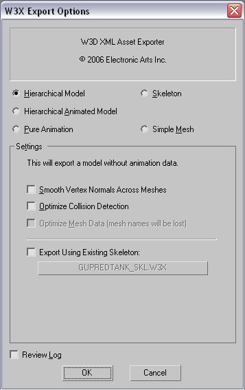
This window appears, select the options as above.
A normal model is just a hierarchical model and you don't want a skeleton (you won't have that option already filled in unless you've merged your model into one of EA's sample models to save time).
Click "OK" and let the exporter run, once it's finished you've completed your work in 3ds Max.
There are a couple of errors you can encounter at this stage, these are the two I have come across so far:
"<i>Invalid texture name "none". Please check the shader material.</i>" - This appears when you haven't assigned a texture to a part of your shader which requires one. Make sure you have a texture for the diffuse, normal, specular and housecolor maps (and reflection if it's a Scrin unit).
"<i>Mesh "MESHNAME" has invalid material. Materials have to use "DirectX 9 Shader Material" and there can only be one per mesh.</i>" - This appears when you have applied a material which is not a DirectX 9 Shader material, or when you have applied more than one material to a single mesh.
Now that your file is out of Max you can start worrying about getting it into the game.
Go to your C&C3 Mod SDK directory and open the folder "Mods", within this folder create a new folder with the name of your mod. I'm going with "TutMod1". Open your mod's name folder and again create a new folder called "data". Navigate back to the "Mods" folder and open "SampleMod/data/", copy and paste "Mod.xml" into "Mods/YOURMODNAME/data/". "Mod.xml" tells the mod builder what files to include for this mod.
Navigate back to your base C&C3 Mod SDK directory and open "CnC3Xml/GDI/Units/", then copy and paste "GDIPredator.xml" to "Mods/YOURMODNAME/data/". This is the code for the GDI Predator Tank, you'll need to untick read only in this file's properties.
Open "Mod.xml" in your mod "data" directory and delete everything between
 and
and  (everything between these two is specifying files for the mod) except for
  (these two lines specify files that should be in every mod).
You then need a new line like this (with "YOURMODNAME" as the name of your mod directory):

This is telling the mod builder to include the GDIPredator.xml file that you copied in earlier.
Open "GDIPredator.xml" and find (CTRL + F in notepad/wordpad) "ModelConditionState" (without the " marks). You'll jump to the first of several condition states for the unit. "ParseCondStateType="PARSE_DEFAULT"" and no "ConditionsYes=" line means this first state is the normal state a unit is in when first created (without the Kane Edition content enabled).
Change "GUPredTank_SKN" to the name you exported your model with out of Max (for me it's "GUTiger"). If you have the Kane Edition (and its content enabled) you need to find "ConditionsYes="USER_5"" and change GUPredTank_SKN here too (this is for the Kane Edition content normal state, in which units can be set to have a specific Kane Edition skin if required).
At the very top of the file is an "Includes" section, you need to clone one of its entries and make it reference your model name ("GUTiger" for me).
If you named your bones and meshes with the EA names you don't need to make any more changes in "GDIPredator.xml". Otherwise you need to find "ExtraPublicBone=" and add your muzzle flash and tread print effect bone names, change TrackMarksLeftBone= and TrackMarksRightBone= to show your tread print bone names for left and right, change TurretNameKey= and TurretPitch= to your turret and barrel mesh names, change the four instaces of "TreadsStop", "TreadsMove", "TreadsLeft" and "TreadsRight" to your tread mesh names and change "BoneName="FXMUZZLEFLASH"" to point to your muzzle flash mesh.
Now head back to your base Mod SDK directory, and go into the "Art" folder. In here you need to put your .tga textures into a folder named with the first two letters of the texture name. You also need to go to "Art/HC/", copy paste "HC_EUlorienwarrior.xml" into the folder with your textures. You need a copy of this file for every texture file. Rename the .xml copies to have the same filenames as your .tga files, then open each one and change "id="HC_EUlorienwarrior"" and "File="HC_EUlorienwarrior.tga"" to the name of each texture file (make sure the "File=" has the .tga extension).
Your model should also be in a folder in "Art" with the first two letters of it's name. All my textures and my model end up in "Art/GU/".
You've now got everything done except building and loading the mod.
Go to "Start" then "Run" and type "cmd", then click okay. The command prompt opens (cmd.exe). You need to get the command prompt to the folder on your PC which contains buildmod.bat (this should be your base C&C3 mod SDK directory).
To do this type "cd" (without the " marks), then a space, then the path to your directory (for me this means "cd c:\cc3 tools\Mod SDK\") and press enter.
The command prompt navigates to your directory and the start of the line should change.
Now you need to run the mod builder, so type "buildmod.bat" (without the " marks) followed by a space, followed by the name of the folder you made for your mod (for me this means "buildmod.bat TutMod1") and press return.
The builder will now run. You'll get alot of errors saying it can't find files, this is just because GDIPredator.xml references alot of files that are already in the game's .big files - there's no need to add them again so these errors can be ignored.
When it's finished the command prompt will display the directory again and wait for another command, you can close at this point.
Now head to "My Documents\Command & Conquer 3 Tiberium Wars\mods", you'll notice a folder named the same as your mod folder was - open this folder.
You now need to create a .skudef file, you can do this with notepad or similar as it's basically a text file. This file needs to be given a name for your mod to show in the launcher (a proper name, less than 15 characters) followed by "_VERSiONNUMBER" with "VERSiONNUMBER" being a number like 1.0 (mine ends up being "Tut Mod 1_1.0.skudef").
In this file you need two lines of text. One should be "mod-game 1.8" (change 1.8 to reflect future patch versions) and the other should be "add-big MODNAME.big" (with MODNAME.big being the .big file which shares the same name as your mod folder).
Insert your game disc and when the launcher appears select "Game Browser", then the "Mods" tab. You'll get a list of installed mods.
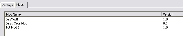
Select your mod and click the launch button, the game will start up (a bit slower than usual).
When the game starts, begin a new skirmish game and build a Predator tank, you should now see your model in all its ingame glory.
Happy modding,
Daz.
Comments
Display order: Newest first
JackTheCrack - Monday May 31, 2010 - 4:05
Hi, are you perhaps still moddeling in CNC3? I'm not looking for a moddeler I'm just looking for an expert to talk to me for a few minutes over some chat program (IRC, MSN, XFIRE would be best) because I have some questions about the subject as I'm trying to import an already existing model with everything from another game but it kinda makes it even harder, would appreciate some small help.
--------
Sorry for tripple comment I have internet problems and I didn't know if the message got through :$
Daz - Wednesday September 12, 2007 - 6:06
Models and textures should only be in the same folder if they have the same starting letters.
Textures, and their .xml files, need to be in a directory named after the first two letters of the filename. GUPredator.tga goes in Art/GU for example.
I don't think that's why you're getting the w3x error though, it's not worth even acknowledging that because it's probably because of the export error.
fr0st988 - Tuesday September 11, 2007 - 3:41
No.Model and textures in the same folder.I have 3dsmax9, and all plugins in same folders, like in SDK folder.I can't add any of my models in w3x to my mod, then i creating the mod, BuildMod.bat saying the same error, that i have in W3xViewer.
Hostile - Monday September 10, 2007 - 11:47
The model and textures used do have to be in the same folder when using w3x viewer. Perhaps that might be it?
Daz - Saturday September 8, 2007 - 11:20
That's not an error I've encountered, I can only suggest you may have installed the plugins incorrectly.
fr0st988 - Thursday September 6, 2007 - 1:37
I'm having some troubles with models.I create model of tank, set all path to textures, shaders.Then i exporting model, in log file 3dmax9 says me, that he cant find ShaderAssetBuilder.exe.And the model exporting without it.But then i launching W3Xview, there this misstake: XML validation error encountered in '../CnC3/Mod SDK/Art/Nu/nunodtnk.w3x' near line 13: The 'X' attribute is invalid - The value '0.000000' is invalid according to its datatype 'http://www.w3.org/2001/XMLSchema:float' - The string '0.000000' is not valid Single value.
Rebelmoon - Sunday September 2, 2007 - 11:01
Nevermind, I forgot to add the cnc3 fx folder to the user paths so it was defaulting to what it could find, my bad.
Thanks,
cheers,
Rebelmoon
Daz - Sunday September 2, 2007 - 9:01
Not sure what's happening there Rebelmoon, it should be using defaultw3d.fx.
You could try setting it to that manually, but it might not have retained the settings for the animation.
Rebelmoon - Sunday September 2, 2007 - 0:21
I'm having an issue, when I add the move and stop shaders taken from the treads max file, it's using default.fx with no spot for the base & secondary textures as instructed. any ideas on what I'm doing wrong?
Cheers,
Rebelmoon
Hostile - Saturday September 1, 2007 - 20:33
This is a very detailed tutorial. I can only assume it's going to be one of our most popular as time goes on. I know I'll be referencing it quite abit. Daz you did a great job.